FEM Analysis of the DC current flowing through the connector. Computing the value for the ohm resistance.
Initial Situation
RJ45 Connector
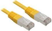
RJ connectors are standardized by the U.S. Federal Communications Commission (FCC) connectors for communications cabling. Goal is to FEM-compute the Ohm Resistance of one cable inside the connector.
 Picture: RJ45 Connector
Appropriate Method
3D Electrokinetic Solution
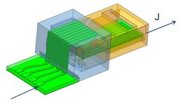
The Connector is modeled in NX CAD and then transferred to the Advanced Simulation module. Using the Magnetics solver a solution type "3D Electrokinetic" is performed. The material (copper) is assigned from the library and the mesh is a standard tetrahedral type. In the output requests the ohm-resistance is activated.

Result
Ohm Resistance and Current Distribution
The calculated Ohm resistance is 0,00512697 Ohm.
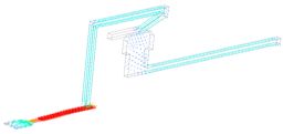
The next picture shows the computed current distribution in the cable.

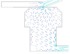
And the following picture shows in detail the contact area.


