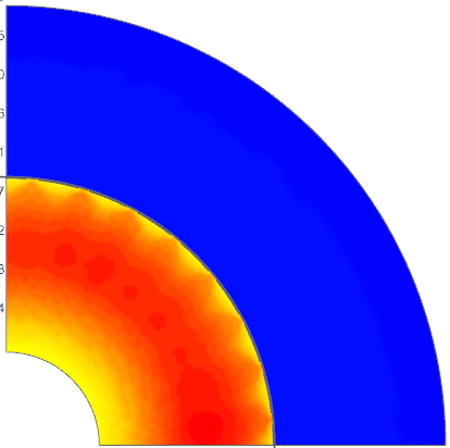
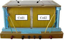
 The Coupled Thermal solution describes the distribution of temperature fields due to losses from electromagnetic solutions or due to applied thermal loads.
Features
- 3D coupling with several other solution types
- Transient or Static.
- Coupling with frequency domain electromagnetic solutions. E.g. for AC heating over time.
- Temperature dependent material properties.
- Thermal Coupling - Interface Resistance
- Outputs Plot
- Temperature, Temperature Gradient, Temperature Conductive Flux
- Outputs Table
- Temperature Maximum, Temperature Minimum
Examples
| HV Transformer | ||
 |
Theory and Basics
Formulations
The basis equations:
(1) (lambda grad T, grad T)Ω
+ Dt (Rho Cp grad T, T)Ω
- (0.5 sigma (-Dt a - grad v), T)ΩC (freq. domain)
- (HeatFlux, T)Ωs1
- ((ConvCoeff - AmbiTemp), T)Ωs2
= 0
lambda: thermal conductivity, Rho: density, Cp: thermal capacitance, sigma: electric conductivity, Heatflux: applied heat, ConvCoeff: thermal convection coefficient, AmbiTemp: ambient temperature.


