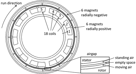
In this tutorial a permanent magnet electric motor is analyzed for torque. Notice that there is also a video of this tutorial in https://magnetics.de/index.php/learn .
For this model setup we want to use the feature ’AutoFEM’ that allows to perform this process highly automatized. Some preparations in the CAD (already done here) are the following. The faces of the CAD model have names. When building the fem model with ’AutoFEM’ we will take advantage of these preparations. To assign names to a CAD face you can select a face and then go to RMB properties. Follow the steps:
Download the model files for this tutorial from the following
link:
https://www.magnetics.de/downloads/Tutorials/6.CouplMotion/6.4ElectricMotor.zip
Open part ’ElectricMotor.prt’.
Start Simcenter and the Pre/Post application and chose function ’New FEM and Simulation’.
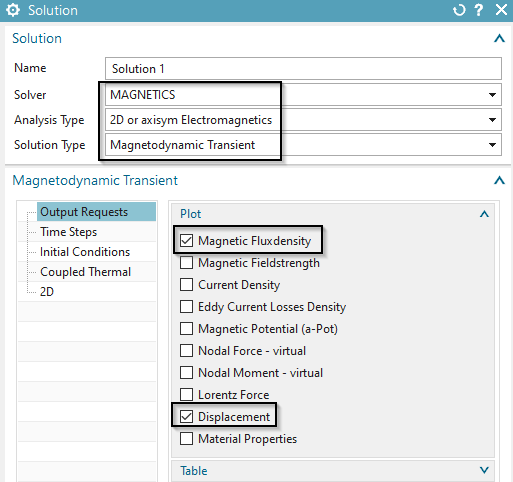
Switch off ’Create Idealized Part’, set the Solver to ’MAGNETICS’ and ’Analysis Type’ to ’2D or axisym Electromagnetics’.
Choose the solution type ’Magnetodynamic Transient’.
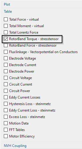
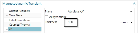
In the dialog Solution set the settings in registers ’Output
Requests’ and ’2D’ as shown in the next picture. OK.
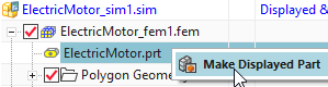
Change the displayed part to the Fem file.
As a prerequisite step add the required Materials to the local
libraries; to do so follow the workflow below.
Hint: This prerequisite step must be done for an AutoFEM simulation with
automatic Material assignments; more precisely said materials must be
added to the ’local materials library’ first, in order to be properly
assigned later by the AutoFEM function. Note that this must be done
before the usage of the AutoFEM function.
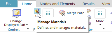
First, Select the ’Manage Materials’ button
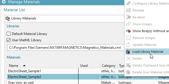
Then, right click on the material ’ElectroSheet_Sample2’ from the
Magnetics Library and select ’Load Library Material’, to load this
Material into the local material Library.
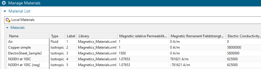
Repeat the last step for the other four required materials (see
picture below). After completion the Local Materials List looks as shown
below.
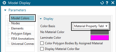
For easier display of colors: RMB on the Fem file, choose ’Edit
Model Display…’, register ’Element’ and set the ’Color Basis’ to
’Material Property Table’. This will later make the meshes look in
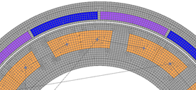
different colors as shown in the below picture right side.
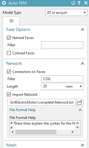
Choose the function ’Auto FEM’ ![]() from
the Magnetics toolbar and choose the register ’2D’. Activate the
settings as shown in the picture.
from
the Magnetics toolbar and choose the register ’2D’. Activate the
settings as shown in the picture.
Hints:
’Named Faces’: All faces that have names in the CAD part will be found and there will be groups created for them in the Fem part.
’Connectors on faces / Filter’: All faces that have a name starting with ’COIL’ will be found. A connector element will be created on those faces. Connector elements are necessary to connect 1D circuit networks to the finite-element mesh. The length of those connector elements will be 20 mm. This setting only plays a role for visibility effects. Each connector element will have two points (A and B) which can be understood as the coil ends.
’Import Network’: The file ’Network.txt’ that is chosen contains definitions for 1D circuit network elements. Those elements contain the winding scheme in our case. Take a look into this text-file to see the definitions.
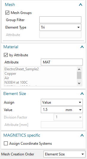
’Mesh Groups’: This option leads to a meshing of all groups that correspond to the value in the ’Group Filter’. If the ’Group Filter’ is empty as in our case simply all groups will be meshed.
’Element Type’: The meshing will be done using the given element type.
’Material’: The option ’By Attribute’ will search for the given attribute (’MAT’ in this case) on faces of the geometry to select a material.
’Element Size’: The size for the elements. Hint: You can use expressions here. This makes it easy to change the mesh sizes later.
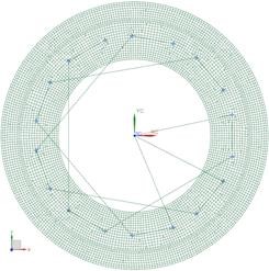
Press OK in the Auto FEM dialog. The network and meshes are created.
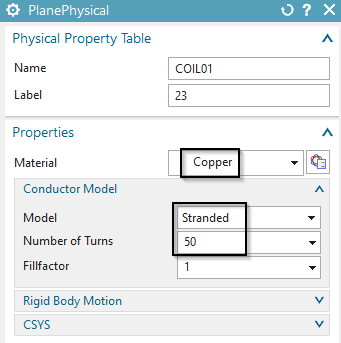
Edit the physical properties of the coils:
First, edit the physical of the first coil (i.e. COIL01). Apply
the settings for ’Material’ and ’Conductor Model’ as shown below.
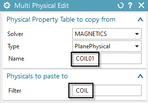
To copy the properties of this first coil to all other coils you
select the button ’Multi Physical Edit’ ![]() from the Magnetics toolbar. Insert the name of the
physical to copy from ’COIL01’ and ’COIL’ as a filter for the physicals
to copy to, OK.
from the Magnetics toolbar. Insert the name of the
physical to copy from ’COIL01’ and ’COIL’ as a filter for the physicals
to copy to, OK.
Maybe you check some other coils to verify they now all have the same properties.
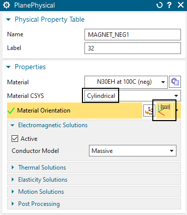
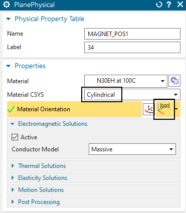
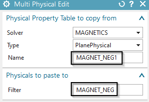
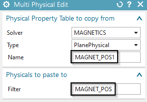
Edit the magnets:
Modify the physicals of the magnets ’MAGNET_NEG1’ and
’MAGNET_POS1’. Set the ’Material CSYS’ to ’Cylindrical’ and choose for
the ‘Material Orientation’ the absolute ![]() coordinate system. See the settings as shown in the next picture.
coordinate system. See the settings as shown in the next picture.
Again use the ’Multi Physical Edit’ to copy these properties to
all other ’MAGNET_NEG’ and ’MAGNET_POS’ magnets, respectively.
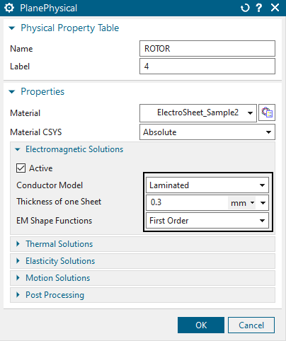
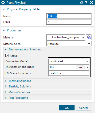
Edit the Iron: The Rotor and Stator should be set to ’Conductor
Model’ ’Laminated’. Otherwise the default model ’Massive’ would be
active and this would result in strong eddy current effects (if the
solution is dynamic). So, modify the two physicals as shown in the
following picture.
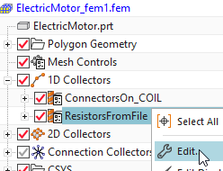
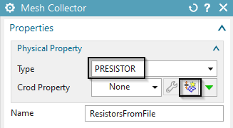
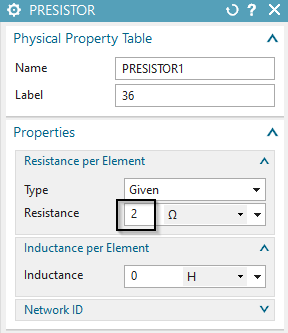
Edit the resistors in the 1D network: Edit the mesh 1D collector
’ResistorsFromFile’. Create a new physical there and insert a resistance
value of 2 ohm. Hint: This value only influences results if the motor is
driven by voltage.
Switch to the Sim file.
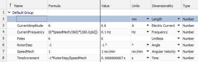
Create parametric expressions: Create the following expressions.
To create them, either use the dialogue (Menu, Tools, Expressions).
Alternatively run the journal ’CreateExpressions.vb’ in the part
directory to automatically create them. (Menu, Tools, Journal, Play,
Browse and select the vb file, Run)
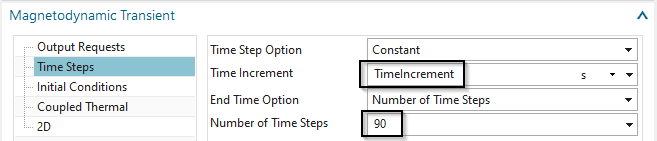
Edit the solution and set the
’Number of Time Steps’ to 90
’Time Increment’ to the newly created expression
‘TimeIncrement’.
Define the rotor motion:
Create a simulation object of type ’Enforced Motion 2D’. Accept the default type ’Revolute by Moving Band’.
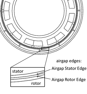
Select the ’Airgap Rotor Edge’ (outer) and the ’Airgap Stator
Edge’ (inner).
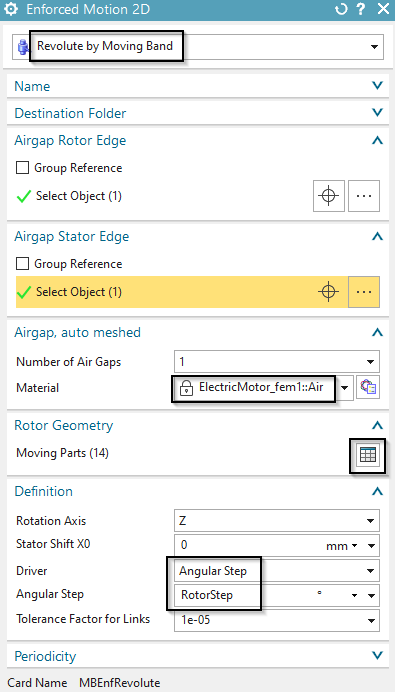
Assign Air for the material at the air gap.
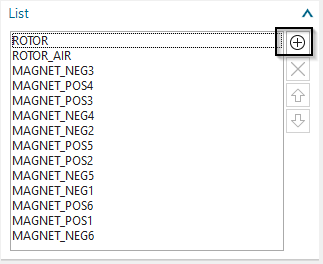
Also, at ’Rotor Geometry’ select the ’Moving Parts’.
These are ROTOR, ROTOR_AIR and all Magnets as shown in the below
picture.
Enter the expression ’RotorStep’ in the field ’Angular Step’.
Click OK to create the joint feature.
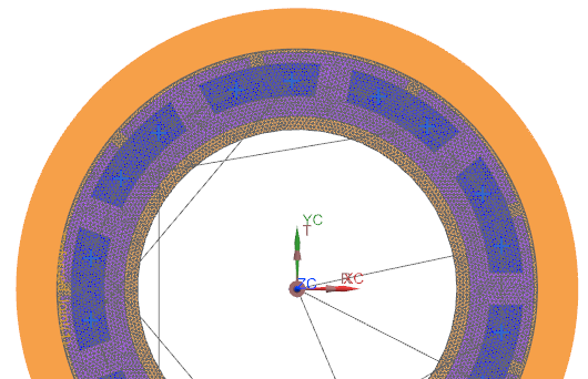
Define current for phase u:
blank all 2D meshes.
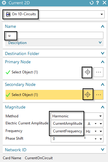
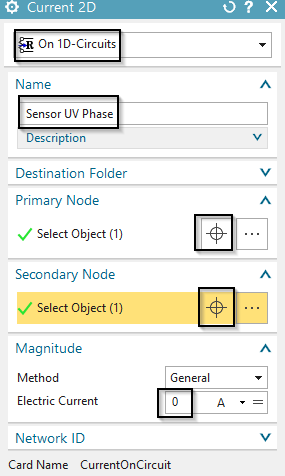
Create a Load ’Current 2D’ with Type ’On 1D-Circuits’ and set the Method to ’Harmonic’.
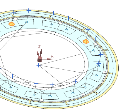
For ’Primary Node’, select the point that is marked in the picture as ’U phase’. (Hint: The node is on the z=0 plane)
For ’Secondary Node’ select the starpoint.
For ’Electric Current Amplitude’, key in the expression ’CurrentAmplitude’.
For ’Frequency’ key in ’CurrentFrequency’.
The ’Phase Shift’ stays zero for phase u.
Assign name ’u’. OK.
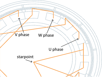
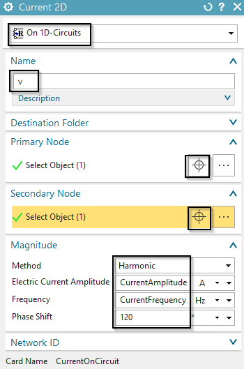
Define current for phase v and w:
Repeat the last steps with exception of the ’Primary Node’
selection and ’Phase Shift’. For phase v use 120 degrees and for phase w
use 240 degrees.

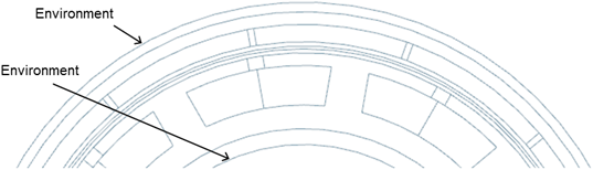
Define the environment condition:
Create a constraint of type ’Zero Potential - Flux tangent’ on
the two circular edges (outside and inside) shown in the picture.
The model is now ready to solve, but in a first step we should find the correct rotor position. Normally for synchronous motors, this is the position of maximum torque. So, we have to find this and then set the rotor to that specific angle. One way how to find this is to run the motor without motion and check for torque. Because the rotor moves in negative direction we have to find the max negative value, e.g. the minimum.
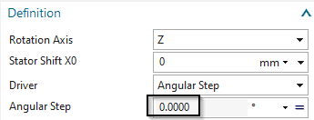
Edit the enforced motion joint and set the ’Angular Step’
(temporary) to 0. We want to fix the rotor and only turn the currents to
find the maximum torque angle.
Solve the solution. (this takes about 3 minutes because of the nonlinear materials)
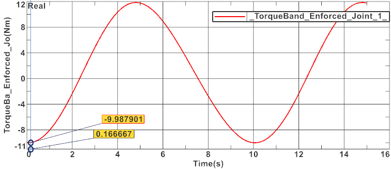
Show the torque result graph and indicate the first
minimum.
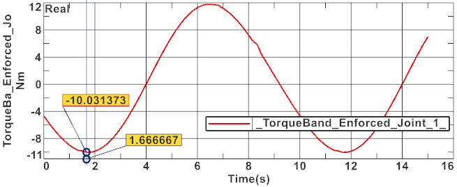
The torque shows a first minimum at 1.667 sec. Let’s transfer this time to the corresponding rotor angle: Because 15 sec represent 90 degrees the minimum is at \(1.667 *90/15 = 10\) degrees.
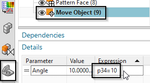
Change the rotor to minimum torque start position:
Set the displayed part to the CAD master ’ElectricMotor.prt’
Expression p34 is responsible for the rotor angle. Change this
from zero to 10 degrees.
Change to the Fem part. Press the Update button ![]() .
.
Change to the Sim file.
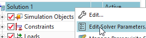
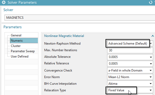
If the model does not converge, change the numerical settings to
help the solution to converge better. We use a fixed relaxation instead
of an adaptively controlled. Therefore,use right mouse button on the
solution and ’Edit Solver Parameters’. In register ’Numeric’at box
’Nonlinear Magnetic Material’ switch from ’Program Controlled’ to
’Advanced Scheme (Default)’. Set the ’Relaxation Type’ to ’Fixed
Value’.
Rerun the solve and display the torque graph again. Verify that
it now starts with minimum torque.
Close the graph display.
In the Enforced Motion, set the ’Angular Step’ back to expression ’RotorStep’.
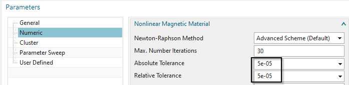
For a higher accuracy result of torque, decrease the tolerance in
the Newton scheme: Go to ’Edit Solver Parameters’, switch to register
’Numeric’ and change the ’Absolute Tolerance’ and ’Relative Tolerance’
both from 5e-4 (default) to 5e-5.
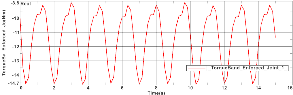
Solve the solution and display the torque graph again. It should
look similar as the next picture.
Close the AFU file.
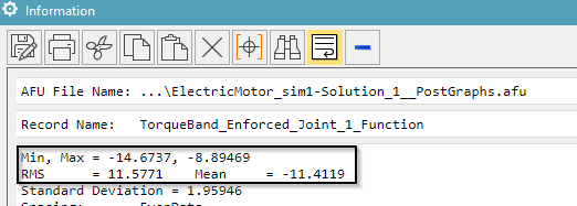
Check for torque ripple: Use right mouse button on the torque
graph and use the function ’Information’. In the information window
there are minimum and maximum values as well as the mean value of the
graph shown. The ripple is the difference between min and max.
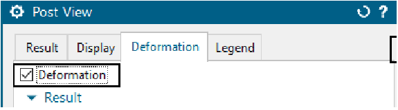
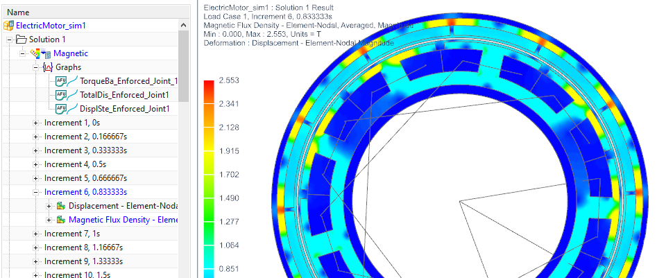
Display rotation: To show the motion of the rotor, first display
a plot result. In ’Post View’, register ’Deformation’, activate
’Deformation’.
and then use the green buttons ’Next Iteration’ ![]() . Alternatively, use the animation feature.
. Alternatively, use the animation feature. ![]() .
.
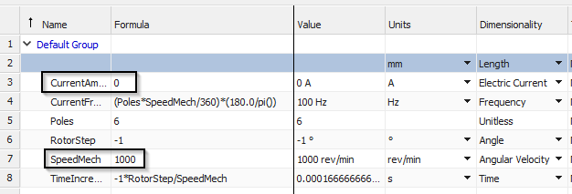
We now want to run the motor with 1000 turns per minute. So, change the expression ’SpeedMech’ to 1000 rev/min. (Menu, Tools, Expressions)
To analyse for voltage, we want to run the motor with zero
currents. So change also the expression ’CurrentAmplitude’ to 0 A.
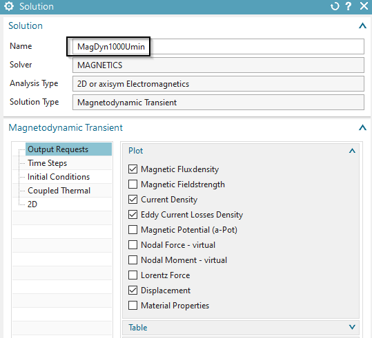
We do not want to overwrite the existing solution. Thus, clone the solution (right mouse button on solution 1, ’Clone’) and rename the new one to ’MagDyn1000Umin’.
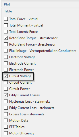
Set the output requests as shown in the picture. The ’Circuit
Voltage’ request will calculate voltages in all circuit elements.
For the measurement of voltage between two phases you create a
new current of type ’On 1D-Circuits’ with zero amperes between the
desired network points. Use for instance the two points U and V. Name
this load ’Sensor UV Phase’.
Solve the new solution
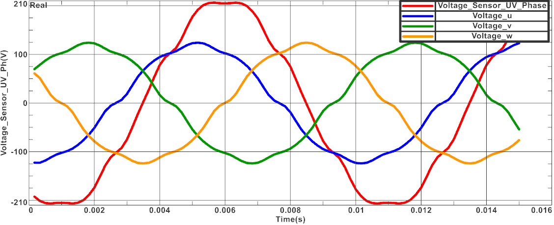
Display the graph results for the voltages in the three phases
and the new sensor. This should look like in the following
picture.
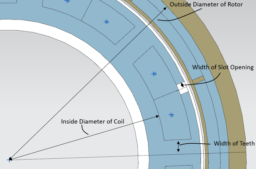
In the last part of this tutorial, we intend to optimize the permanent magnet synchronous motor. Therefore, we use the additional program Design Space Exploration, which is a limited version of HEEDS, that can be used only with Simcenter 3D. The goal of this optimization is to maximize the RMS of the Torque and to minimize the Ripple. We thus adjust the Outside Diameter of the Rotor, the Inside Diameter of the Coil, the Width of the Slot Opening and the Width of the Teeth.
Before setting up the Optimization in HEEDS, we need to make sure that all necessary results are available.
Prepare the Model in NX
Download the model files for this tutorial from the following
link:
https://www.magnetics.de/downloads/Tutorials/6.CouplMotion/6.4ElectricMotor.zip
Open the file ‘ElectricMotor_sim1.sim’. Hint: You may also use the solution that was created in the previous section.
Change to the Part file and set the expression p18 to 220 mm.
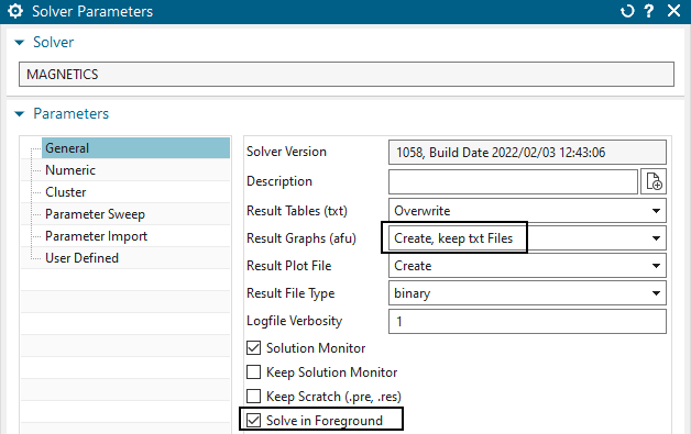
Switch to the Sim file and set the ‘Result Graphs (afu)’ within
the ‘Solver Parameters’ to ‘Create, keep txt files’ and activate ‘Solve
in Foreground’.
Solve the Solution once to create the txt files.
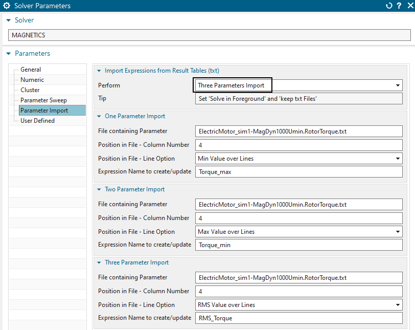
Now import three Parameters in the ‘Solver Parameters’ menu.
Choose for every Parameter the txt file ‘ElectricMotor_sim1-MagDyn1000Umin.RotorTorque.txt’ and copy it into the window.
Set up the Parameter Imports as shown in the picture below.
Hints: The Torques are shown in the fourth column of the file. As
the lines in this case are negative, we set the Line Option for the
maximum Torque to the Minimum Value.
Solve the Model again and save it before changing to Design Space Exploration (HEEDS).
Set up the HEEDS run.
Open HEEDS and save your HEEDS-project in the same folder, were you also have saved the Sim file. Name it ‘ElectricMotor_HEEDS’.
In order to minimize the solution time, set ‘Num. designs to
execute simultaneously’ to five.
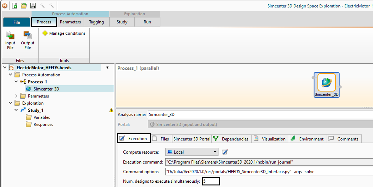
Input the Sim file which you have prepared in advance. HEEDS will
then automatically upload the Fem File, the prt file and also create the
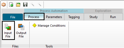
output file. After loading, continue without ‘Auto Tagging’. Click on
‘Process’ and ‘Input File’.
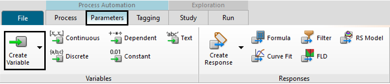
The next step is to create the ‘Variables’. Click on ‘Parameters’
and ‘Create Variable’.
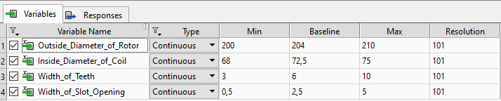
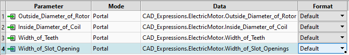
Create the variables as shown in the picture below. HEEDS will adjust these variables to optimize the objectives. In this example we have chosen geometric variables (see below fig.).
Hint: You always define a minimal value, a maximum value and the
baseline value, which is set up in your NX model and defines the first
Design, the so called ‘Baseline Design’.
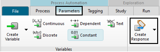
The next step is to create the responses. Therefore, click on
‘Parameters’ and ‘Create Responses’.
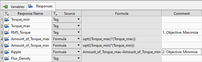
Create the ‘Responses’ as shown in the picture below.
Hints: In this example the minimal and the maximal torque is
printed out with a negative value. To calculate the torque-ripple we
want to use the value of these responses by creating new responses and
calculating the values. Then we will use the type ‘Formula’ and input
the calculation. By clicking ‘Apply’ we add the formula to the
response.
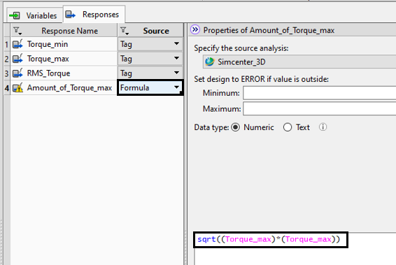
Create a formula also for the ripple. Hint: one response of the solution must be added to generate results. Therefore, the Flux Density is also created as a response.
Your list of responses should look like the one in the picture
below.
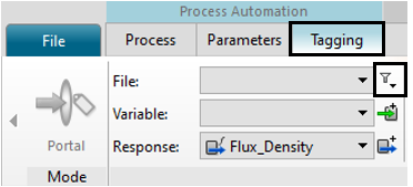
Now follows the part of ‘Tagging’. Here, we will connect the
variables and the responses to our Input File and Output File. First,
choose the input file by clicking on the button in the picture
below.
Choose the Sim file marked green as input file and ’Tag’ the variables with the ’CAD_Expressions’.
Hints: To ’Tag’ a variable choose it from the list of variables
(top), click on it in the list of expressions and tag it with clicking
on the button ’Tag’.
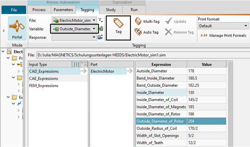
After tagging every variable the list should look like the one in
the picture below.
Do the same with the responses. Choose the Sim file marked blue as Output File and tag the Torque_max, the Torque_min and the RMS_Torque from the list of ’CAE_Expressions’.
Choose the Flux_Density in the list of the solution and set the
filter to ’Max’ to get the maximum value.
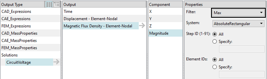
Afterwards, the list of tagged responses should look like the one
in the picture below.

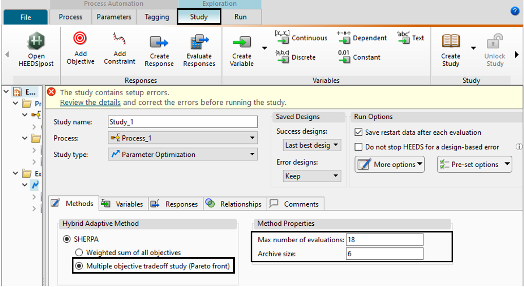
The part of tagging is now done and we will set up a study in the ’Study’ tab.
Choose the ’Multiple objective tradeoff study (Pareto Front)’ as ’Hybrid Adaptive Method’ and set up the ’Method Properties’ as shown in the picture below.
Hint: We choose a minimum value of the evaluations and the
archive size to reduce the time of solving the run to a minimum. For the
creation of more designs you can choose a higher number.
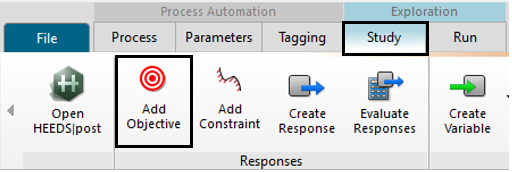
In the next step we will define the two objectives.
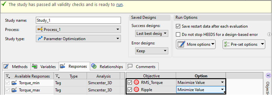
Choose the response RMS_Torque as first objective and maximize the value. The second objective will be the ripple. Choose it out of the list and set the option to ‘Minimize Value’.
Afterwards it should look like in the picture below.
The setup of the study in HEEDS is done. Safe your project.
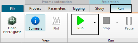
Run the study by clicking on the button ’Run’ in the run
tab.
It will take HEEDS about 45 min to create the designs.
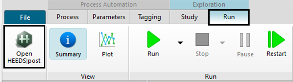
We then want to do some post-processing to evaluate the results
and to choose the best design. To this end open ‘HEEDS post’.
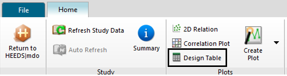
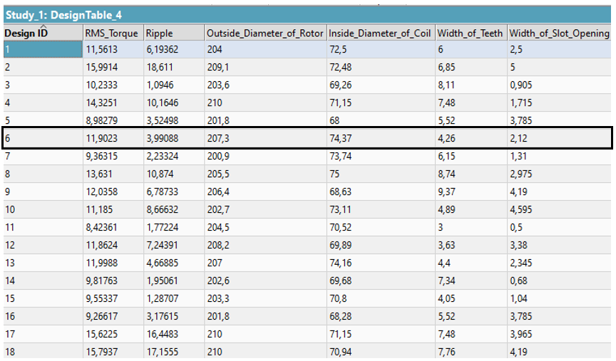
In order to find the best design, we create a ‘Design
Table’.
Choose all variables, the responses ripple and the RMS_Torque
from the list (picture below).
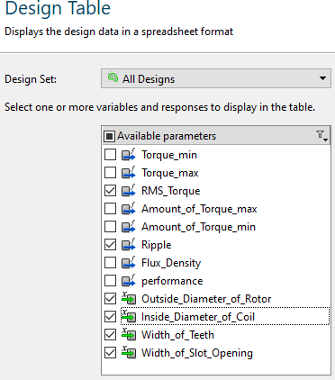
Create the table with ’Finish’.
Out of the 18 designs created, we choose the one design with the
smallest ripple value and the highest RMS_Torque. With design 6 we can
reduce the ripple by 25 % and the RMS_Torque increases slightly compared
to the Baseline Design. Thus, the motor model definitely is
optimized.
The tutorial is completed.